In-Process, Real-time Results
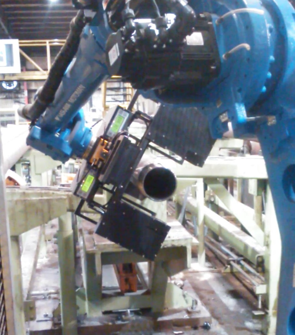
More manufacturers are improving their precision machining by adding in-process automated inspection as the final step in production quality control. Autonetics non-contact gaging technology benefits our clients by providing higher quality results with limited operator interaction. As a result, labor cost is reduced and because the process is automated without compromising production, faster throughput and fewer scrapped parts contribute significantly to increased profitability.
- 100% inspection of all callouts on every pipe
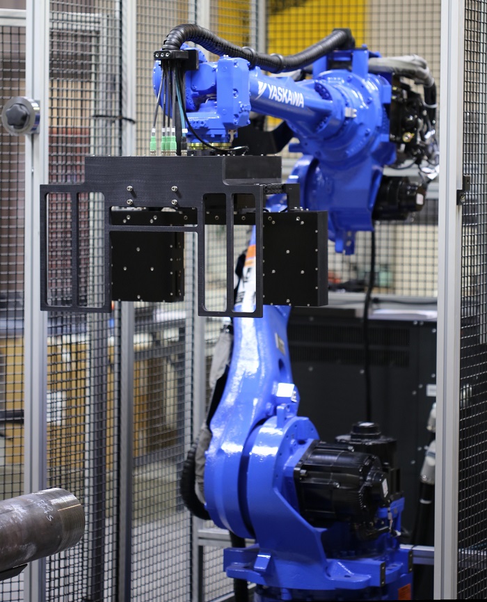
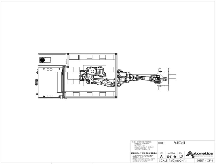
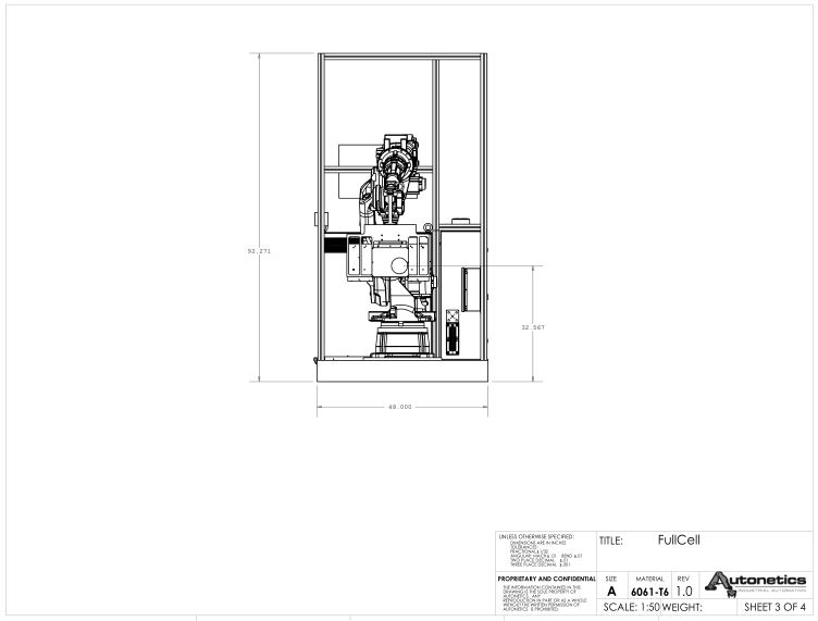
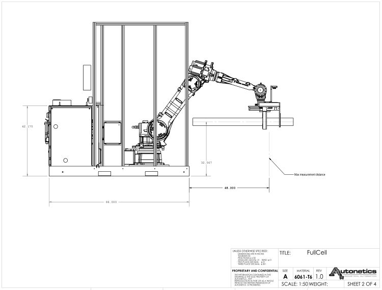
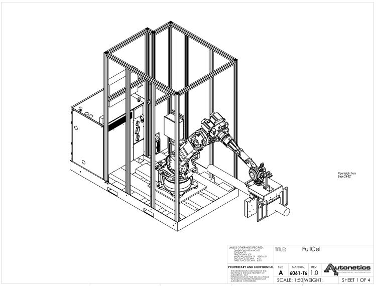
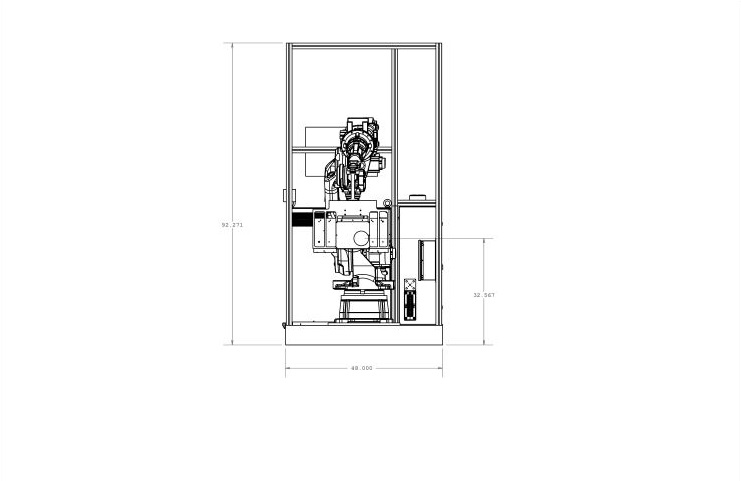
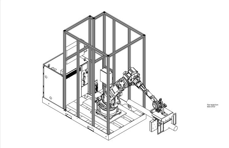
- Full Turn-Key robotic system AGU 3.0
- Factory floor ready metrology proven in harsh mill environments
Autonetics serves the API, Premium connections inspection segment of the oil and gas industry and the precision, machine thread manufacturing field. We present a full line of new, state-of-the-art inspection equipment, manufactured in-house with the latest technologies and innovations available worldwide.
Autonetics Gauging Systems have allowed several of our customers to fully automate their thread gauging method as an important adjunct to new, high speed machining lines and pipe mills. The complimentary processes of automated machining and automated gauging, will greatly increase component output to meet rapidly growing market demands while ensuring repeatable quality. The demanding task for achieving repeatable accuracy is accomplished with this multi-capable application that analyzes any given thread form through a number of callout possibilities.
Autonetics gauging software includes the AMS 5.0 Metrology Software Suites. These are time-proven over many successful customer applications including those involving diametrical and plotted thread profiles. Customers thus have confidence that our hardware/software combination, when configured to their application, not only will operate up to expectation but also will exceed the speed and capabilities of manual inspection.
Autonetics user interface is continually updated in real time and designed to give at a glance graphic representation of trends and results. Logical arrangement and straight forward navigation makes for an intuitive user friendly operating system. For details on software operation and general AGU information refer to Autonetics manual 3.1.2
All gauge functions are controlled by individually designed digital I/O controls, which allow the operator to switch instantly between different part numbers and part families. Where applicable the controls compensate the production equipment based on the average deviation from real time results and adjust the cell instantly should any dimension fall out of tolerance. As microprocessors are incorporated into both gauging and machine tools, the simplicity of incremental compensation is replaced by the sophistication of absolute compensation, in which the machine’s position is adjusted by the exact amount that is optimum.
If desired, compensation can be triggered when part dimensions are drifting off nominal, rather than waiting for them to approach tolerance limits. Autonetics gauging controls also accept data from temperature sensors during production and inspection to perform additional machine compensation for thermal influences.
Specifications:
| Temperature operating range | 32ºF to 140 ºF |
| Measurements / sec | 5,200 |
| Sensor resolution | 0.0000393in |
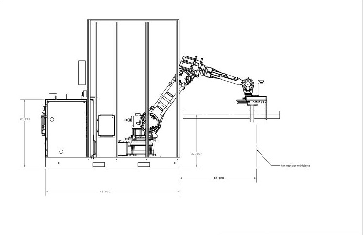
| Maximum Reach | 48in |
| Positioning accuracy | 0.0000019in |
| Overall systems repeatability | +/- 0.0001in |
Basic Features
Autonetics Gauges inspect a wide variety of thread forms including; API, OCTG Semi-Premium / Premium, Buttress, Round, ISO Metric, Unified Inch Screw, Taper as well as custom designed thread forms. Some of the callouts our system measures are:
- Pitch Diameter
- Major / Minor Diameters
- Lead
- Thread Height
- Ovality
- Hand-tight Plane
- Washout Thread Location
- Virtual MRP Gage
- Trailing Flank Angles
- Leading Flank Angles
- Chamfer Angle
- Helix Angle
- Black Crested Threads
- Pitch Cone
- Major / Minor Cone
- Virtual Ring Gage
Hardware:
- Palletized Chassis
- Modular Components
- Quick Disconnect Features
- Advanced Cooling Systems
- Membrane Air Filtration System
- Solid State Metrology Sensors
- 23″ Touch Screen UI
- Visual and Audible Reject Alarms
Software:
- Real Time Data Export
- Logging and Traceability
- Data Analysis and Tracking
- Controlled Administrator Access
- Tolerance Authority
- Thread Profile Display with Zoom and Screen Touch Commands
- I/O Diagnostics and Alarms
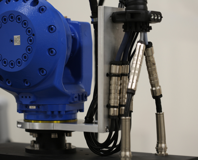
The sensor array is comprised of three critical parts, the seventh axis, the housing and the sensors. High positioning resolution is required of the seventh axis as the thread form is scanned to pinpoint the precise location of thousands of measurements. Autonetics partnership with premier equipment manufactures as well as industrializing and armoring at our facility yields a uniquely suited, purpose built actuator for factory floor metrology. Enclosing the sensors are two (2) matched and sealed, high strength alloy mounts for optimum beam alignment. Incorporating air purging ensures a constant flow of clean, cool air to achieve added protection and low maintenance. Each solid state emitter and receiver of the array is constructed to withstand long term vibration and shock. With no moving parts or fragile mirrors the potted electronics greatly exceeds preexisting laser sensor performance. Our AGX products employ a tool free, quick disconnect feature and IP 69 cable connections designed to allow non-technical personnel to exchange heads in less than ten minutes.
Autonetics industrial, non-contact thread profiling and metrology systems can help you meet demanding requirements in the petroleum, aerospace and high tolerance manufacturing fields.